My doorbell came with a bellpush with a little bulb inside.
It was wired across the contacts. The current flowed though the bell winding. The voltage drop across the bulb was such that the bell wouldn’t sound. When you pressed the button, the bulb would be shorted out and the bell would ring.
After a while, the bulb failed. There was enough room for two bulbs, so I fitted a conventional bulb in one space and an LED in the other. The LED flickered slightly, (it only conducted for half of the cycle of the ac supply), but was brighter and more efficient.
After a further period of time, the conventional bulb failed, followed a day or so later by the LED. Without the bulb, the LED was no longer protected from the back emf from the bell coil.
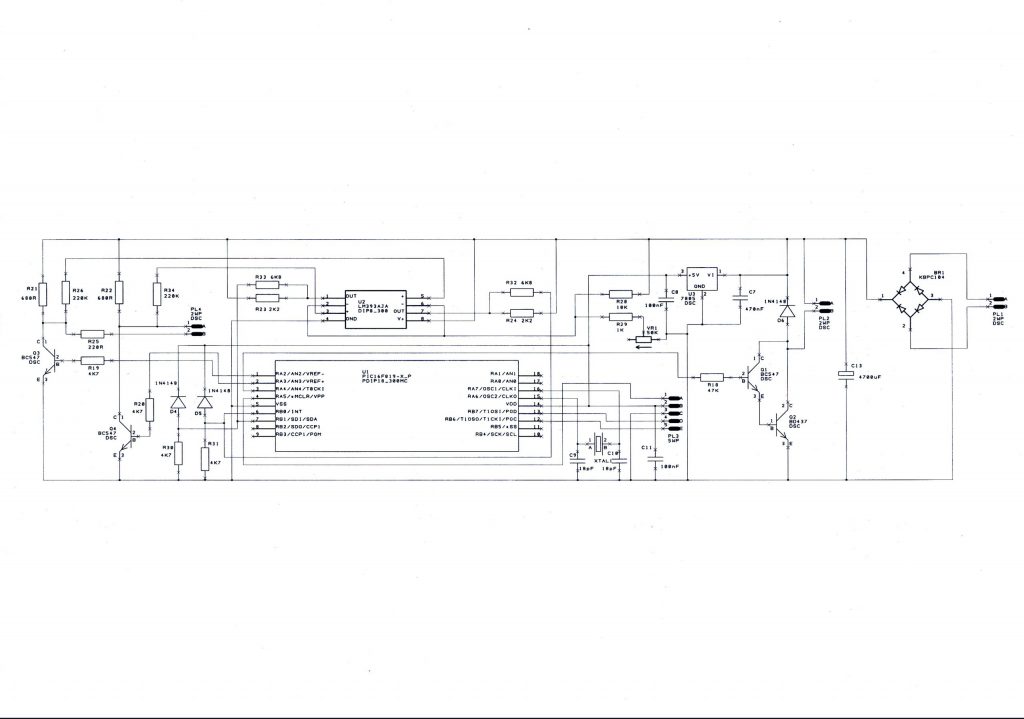
So I set about designing a better circuit:
I fitted two LEDs back to back in the bell push. Using a small PIC, I generated a square wave that was fast enough not to cause any flicker.
I used a pair of potential dividers to detect the voltage change across the LEDs when the switch was pressed. The circuit that operated the bell would only apply power for a brief period, before requiring the push button to be released for several seconds. No more repeated chimes while you’re on your way to the door.
The voltage quoted for the output of the bell transformer obviously assumed some sort of load, as it was considerably higher under no load conditions.