Background
I was about 15 when I built my superhet. It was a valve design based around a project which appeared in Practical Wireless in 1971. My version was housed in three sandwich boxes; the power supply, the audio amplifier and the receiver itself, to which I added an EM84 tuning indicator. It covered the medium wave band and was easily the biggest project I’d ever undertaken.
The specified Denco coils were unavailable in Hong Kong, where I was living at the time. The local offering wasn’t compatible with the triode oscillator in the original design, so I ignored the triode section in the ECH81 and modified the heptode circuit to match the suggested circuit for the supplied coils. It worked fine.
The set was rebuilt several times over the years, in various metal cases, with various improvements, with the Denco coils and a second IF stage being added later.
As with many home built receivers, the weak link was the lack of a frequency readout, made even more difficult by the use of a geared tuning capacitor, which had greater than 360° rotation, meaning any pointer would have be attached to the capacitor itself, rather than the knob.
The answer came with the experience of the university education – not the actual course – but the confidence to design something from scratch.
The idea had been in my head for years – a digital readout. The money was now there, but the technology had moved on – a PIC could have done the job with fewer components, but I had a collection of 4000 series ICs and an unfulfilled ambition.
What’s a Superhet?
A Superhet is an abbreviation for Super Heterodyne, where heterodyne is the mixing of two frequencies to create a beat. In a superhet, the beat, or difference frequency is amplified and processed. The superhet is the design of most domestic radio receivers from the 1930s until the turn of the century, when digital signal processing techniques began to make other options like direct conversion a practical possibility.
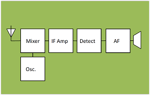
The figure above shows a block diagram of a superhet receiver. In a domestic set, a ganged variable tuning capacitor maintains the frequency of the oscillator at a fixed value above the wanted input signal.
The wanted signal, the oscillator signal and their sums and differences are present at the mixer. Only the difference frequency is allowed to pass through at the Intermediate Frequency Amplifier.
The IF amplifier allows the selectivity of the receiver to be increased before the signal is converted to audio at the detector, then finally amplified and fed to the speaker.
The frequency chosen for the IF is a compromise resulting from several requirements, but a value of around 460kHz is typical for an AM broadcast receiver.
Even under no-signal conditions, the oscillator provides a signal for our digital readout. All we have do is subtract the intermediate frequency from the reading.
The 4 Digit Display
The 4000 series are digital CMOS ICs, popular in the 1980s, but still mostly readily available. A zero voltage on an input or output is treated as a binary 0 and a supply-level voltage is treated as a binary 1.
The devices can store logical states and hence perform both combinational and sequential logical operations.
The 4029 is a counter. For every clock cycle applied to pin 15, the internal count state changes, observable at the four outputs at pins
6,11,14 and 2. The device is configurable to count either up or down
and to count in binary (0-15) or Binary Coded Decimal (0-10). Furthermore, the devices can be cascaded to count multiple digits
and may be preset to any value.
A companion device is the 4511. It can take the BCD outputs of the
4029 and convert them to drive common-cathode 7-segment LED displays.
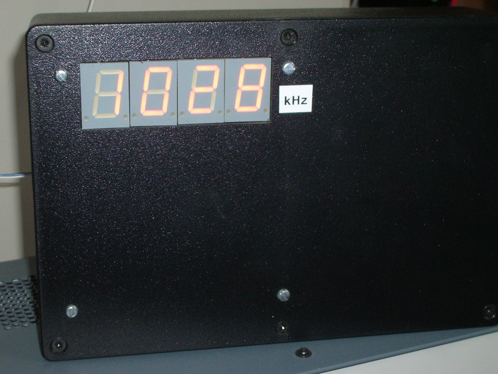
For a medium wave receiver, we need to display frequencies between around 550kHz to 1500kHz. If we make our display show whole numbers of kHz, we can use four digits and refresh the reading every second.
Our local oscillator signal is present even when there is no signal being received. We just need to subtract the intermediate frequency. We do this by preloading the counter with (10000 – the IF, say 460). When the counter starts, the first 460 pulses set the reading back to zero, (i.e 10000 with the most significant 1 not being visible). The remainder of the pulses then count to the value of the frequency being received.
To make the display look nice, we show a static value while the count is in progress and refresh the display when the count is complete. To control the count sequence, we use another counter and use combinational logic to generate control signals at certain count values.
Controlling the Count Sequence
Every second we need to do the following:
- Preload the counters
- Enable the count
- Stop the count after 500ms
- Latch the outputs into the 7-segment displays.
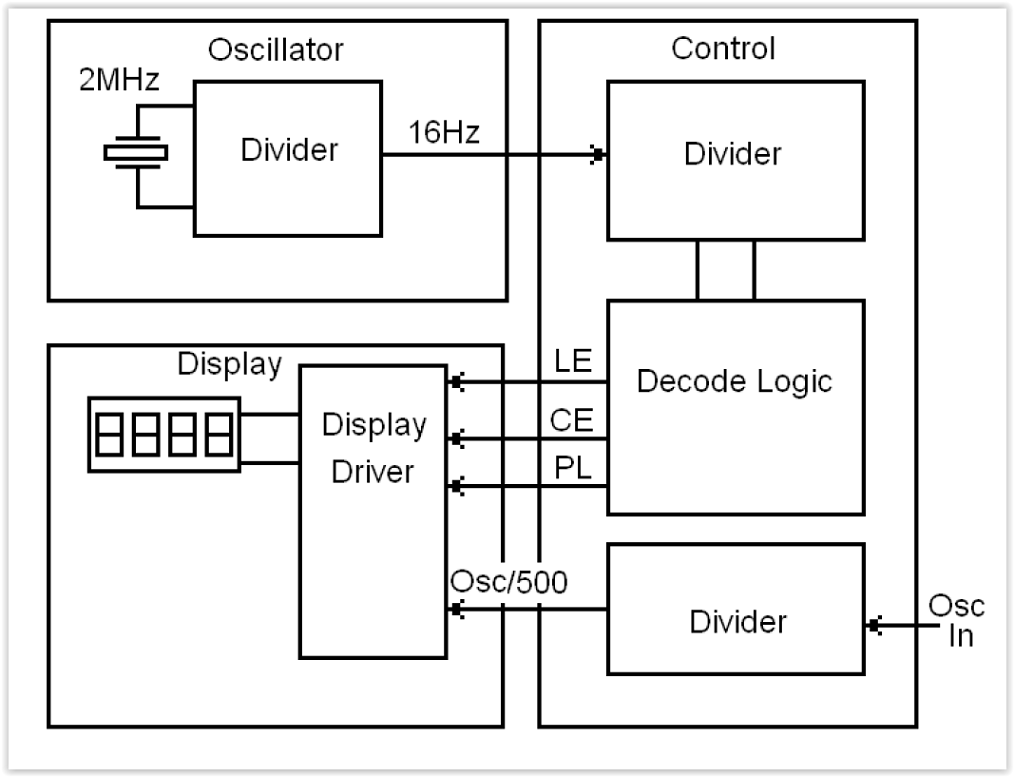
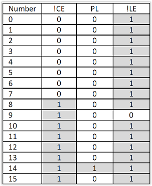
We accomplish the sequence by feeding a 16Hz clock into another 4029, this time configured as a 16-stage counter. We decide in which of the 16 states that we want the above four steps to happen, then use combinational logic to generate the Preload, Count Enable and Latch Enable signals.
Blanking The Leading Zero
As it stands, the display would show a leading zero for readings below 1000kHz. Although there is a blanking input on the 4511, we cannot easily use this, as the number which we may want to blank only exists inside the latch in the 4511. We could store a blanking signal, but an easier way is to force the inputs to a value above nine whenever a zero is detected, thereby producing a value that is displayed as blank by the 4511.
For an AM receiver, the frequencies used mean we don’t have to worry about blanking more than 1 leading zero. Furthermore, unless frequencies above 2MHz are required, the blanking can be achieved using a single transistor – if the least significant bit is not 1, set the other three bits high.
Controlling Oscillator
The 16Hz signal required for the control sequence is obtained by dividing down the output of a 2MHz crystal oscillator. The local oscillator signal also requires dividing by 500. Both of these divisions take place using further 4029 dividers and combinational logic.
Input Signal Conditioning
This part of the circuit needs tailoring to the receiver type. A take-off point on the local oscillator needs to be chosen that won’t load or detune it. Rather than connect a long lead, which may pick up or radiate unwanted signals, it is a good idea to place a high impedance buffer as close as possible to the local oscillator. In the prototype, it was necessary to attenuate the signal to avoid overloading the buffer.
The buffer output is then connected to the Control & Input section with a length of screened lead. There is provision for either amplification or buffering on the Control and Input Section, depending on which components are fitted, before being fed to a Schmitt Trigger for conversion to logic levels.
Setting Up
The key to correct operation of the design is getting a clean signal from the local oscillator; too small a signal will fail to trigger the counter, too large and harmonics could double or triple the reading. Check that the signal is clean over the entire tuning range.
The preload values for the counter stage then need to be set. Assuming a nominal IF of 465kHz, set the jumpers to preload 10000-465=9535. Tune in a station of a known frequency and compare the displayed frequency with the actual station frequency. If the display reads low, then the actual IF is lower than the nominal value chosen, so reduce the 465 in the above equation by the difference in reading. For a wildly inaccurate reading, suspect the input signal quality.
If necessary, the display section can be tested in isolation; the inputs, Clock Enable, Preload and Latch Enable should be connected to pull-down resistors and toggle switches to VDD. Either a single-step or low-speed clock can then be applied and the various stages of operation can be checked out.
Prototype Construction
Depending on the amount of room and the available power supplies, a decision needs to be taken about whether the display can be mounted within the receiver cabinet.
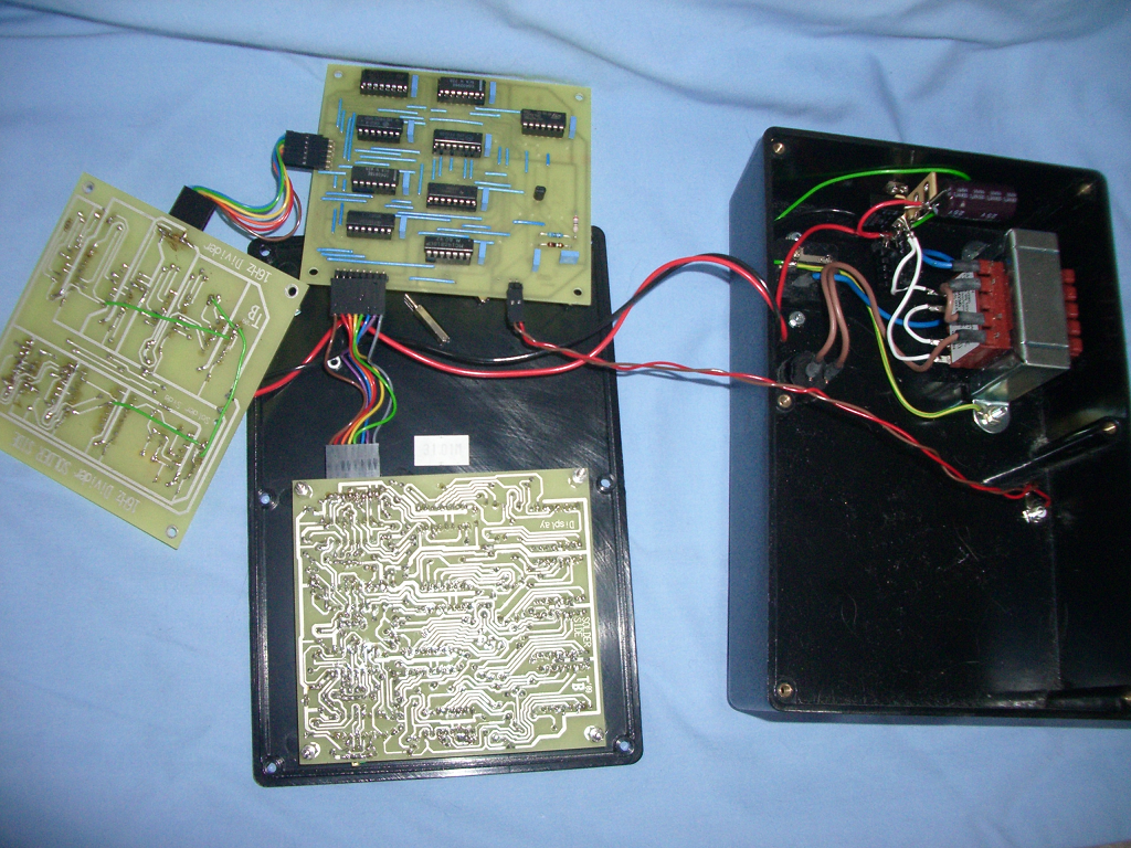
The prototype was built as an external unit, with just the valve buffer within the set. The prototype was built using three single-sided printed circuit boards fitted in a vertical stack.
To allow the design to be checked by computer for connectivity, the board was manually routed as a double-sided design. All the top side tracks were made straight and the ‘via’ holes enlarged. The top layout was then discarded and replaced with wire links.
Sockets for all the ICs are strongly recommended. A 100nF capacitor should be connected across the supply close to every IC. A regulated 12V power supply is required; a 7812 was used in the prototype. Current consumption is largely determined by the size and brightness of the 7 segment displays.
Circuits (DXF and UTSCH) and parts lists available.